Note: This chapter is probably of limited interest to the reader, as it deals with the theory rather than practice of calibrations. It is intended as a ``proof-of-concept-in-theory.'' The next chapters will deal with specific procedures for calibrating different types of data under normal operation.
``Calibration elements'' refers to separable units in the overall calibration of the instrument. There are three categories of these: (1) detector calibration; (2) spatial calibration, including wavelength; and (3) flux calibration. These may be thought of as breaking the instrument into a detector and a spectrograph/camera. For each, we wish to provide mappings between input information and observed information, where the information is either spatial or intensities. The spatial mapping of the CCD itself is assumed to be known.
The goal of the current chapter is to identify the separable elements in each of these categories, understand their dependencies, and identify how they can be characterized. The need for this is driven by several questions:
We wish to identify two parallel paths for deriving and applying calibrations for data reduction. The first is baseline mode -- this is the traditional method, where the user acquires all necessary supporting calibration data and which assumes neither information about nor understanding of the instrument. The other path is a completely automated reduction pipeline, where no information is needed for reduction other than what is contained in the FITS header for a given image. In practice, neither of these paths will be entirely applicable. A completely automated pipeline will probably not provide the necessary accuracy for wavelength calibration and distortion correction. On the other hand, the amount of calibration data needed for slitmask spectroscopy is prohibitive for a single user to acquire (not to mention that instrumentation failure and weather sometimes prevent its acquisition). Therefore, in practice certain elements will be borrowed from the database and others will come from the science images themselves. It will be a user option to decide how many supporting calibrations will be acquired for the user's particular data set.
These elements refer to individual CCDs.
This is easily determined from the overscan region of an image.
This is easily determined by averaging enough bias frames to overcome the readout noise.
This is easily determined by averaging enough long-exposure dark frames to overcome the readout noise.
Pixel-to-pixel variations in the CCDs can be estimated easily by smoothing a flat-field frame by a robust smoothing filter of fairly large pixel scale, and dividing the original image by the smoothed image. [TBD: decide on smoothing filters - probably a combination of spatial medians and gaussians - and on the smoothing length.]
It is possible that pixel-to-pixel variations are not highly
![]() -dependent. Although it is well-known that there are spatial
variations in DQE with color, these are believed due to variations in the
thinning, and the spatial scale for these variations should be larger
than several pixels. If this is the case,
only one high S/N flat need be obtained for the pixel-to-pixel flat.
Otherwise, high S/N flats will need to be acquired in several filters
and/or grating tilts
and interpolated to specific observed wavelengths during pipeline reductions.
-dependent. Although it is well-known that there are spatial
variations in DQE with color, these are believed due to variations in the
thinning, and the spatial scale for these variations should be larger
than several pixels. If this is the case,
only one high S/N flat need be obtained for the pixel-to-pixel flat.
Otherwise, high S/N flats will need to be acquired in several filters
and/or grating tilts
and interpolated to specific observed wavelengths during pipeline reductions.
[Recommended action item: explore color (in)dependence of pixel-to-pixel variations, using LRIS and/or KAST. Eventually can also be tested in DEIMOS in lab.]
These remove vignetting, and are discussed below in flux-calibration.
Fringing is caused by internal reflections in the CCD, and depends on
variations of the thickness of the CCD,
its transparency at a given wavelength, and the angles of illumination.
As fringing appears to be the result of relatively high order ( ![]() )
interference, it is not feasible to calibrate the variations in thickness
directly. Also, the changing illumination may cause a phase shift or
changes in the fringe amplitude. For these reasons, the most direct
method to remove fringes is to take a flat-field through the instrument
with the identical setup as the science observations, that is, same
slitmask, grating tilt, rotator angle, and divide by this flatfield.
)
interference, it is not feasible to calibrate the variations in thickness
directly. Also, the changing illumination may cause a phase shift or
changes in the fringe amplitude. For these reasons, the most direct
method to remove fringes is to take a flat-field through the instrument
with the identical setup as the science observations, that is, same
slitmask, grating tilt, rotator angle, and divide by this flatfield.
Since a slitlet's position affects the wavelength scale, for automated removal of fringing we must treat each slitlet individually. If we have a series of spectral flats at various grating tilts [TDB: determine needed sampling interval] we should be able to choose a flat at similar wavelength to the science observation, and solve for a best-fit phase offset using bright night-sky lines. Note that this requires a special long-slit mask that covers the entire mask length. Note also that this scheme will fail if variations in vignetting produce a significant change a fringe amplitude.
[Recommended action item: explore behavior of fringing with LRIS and/or KAST, particularly with changes in rotator angle in LRIS.]
This is not technically a calibration, nor are there any calibrating database products, but we list CR-removal here as it is specifically a detector issue. CR-removal is a problem without easy solution, although the relatively small sampling scales of DEIMOS will help in discriminating between CRs and real features. [This is currently an unresolved issue.]
We assume the CCD spatial mapping is known (square grid,
15 ![]() m square pixels).
m square pixels).
This refers to astrometric mappings. These are available in approximate form
as CCDCSi ![]() ICS
ICS ![]() FKCS mappings
(see Chapter 2).
In automated mode, the limiting accuracy will be set by the telescope pointing
[
FKCS mappings
(see Chapter 2).
In automated mode, the limiting accuracy will be set by the telescope pointing
[ ![]() 10 arcsec], although the internal relative accuracy will be much higher
[
10 arcsec], although the internal relative accuracy will be much higher
[ ![]() 1 arcsec?]. User identification of a single astrometric reference star
on an image should bring absolute and relative accuracy to the same level.
This should be adequate for quick-look reductions.
1 arcsec?]. User identification of a single astrometric reference star
on an image should bring absolute and relative accuracy to the same level.
This should be adequate for quick-look reductions.
For astrometry adequate for slitmask design, three or more astrometric reference stars distributed across an image will be required. For spectroscopic reductions (where to locate objects in slits), two or more objects with known coordinates will probably be required to set the spatial scale.
Approximate wavelength calibration is available from the mapping of the MF/SMCS to ICS. In practice, precise adjustments will be needed to provide calibrations of sufficient quality for astronomical work. This is necessitated by inaccuracies and unknowns in the system -- for example, measurement errors in mapping camera distortions, flexure, irregularities in the slit structure within the mill tolerances, etc.
Strong night sky lines can usually be used for wavelength calibration adjustments after the wavelength mapping is performed. These adjustments may take the form of a simple zeropoint correction (one nightsky line needed), or full wavelength solution (several lines). The modeled wavelength mapping should be sufficient that strong night-sky lines can be identified without visual inspection by the user.
We identify the efficiencies of various components, and their functional dependence:
![]()
where the superscripts V and R denote vignetting and reflectance, respectively.
 ), and grating reflectance (
 ![]()
where
![]()
or
![]()
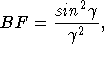
Note that the theoretical blaze function can be written without an implicit
![]() -dependence. We retain
-dependence. We retain ![]() in the blaze function, as there
are sometimes wavelength-dependent deviations from the theoretical relation.
We separate the grating efficiency into:
in the blaze function, as there
are sometimes wavelength-dependent deviations from the theoretical relation.
We separate the grating efficiency into:
![]()
Note that ``grating'' can also refer to the imaging mirror, in which case there
is only the reflectance ![]() -dependence,
-dependence, ![]() .
.
![]()
where the superscripts V and T denote vignetting and transmission, respectively. Note that there is no camera vignetting in imaging mode.
![]()
The simplification and separation of the various efficiencies above allow
us to rewrite all the efficiencies in a more simplified way. Notice that
the position on the tent mirror ( ![]() ) maps uniquely into
input angles at the grating (
) maps uniquely into
input angles at the grating ( ![]() ) and so we substitute those
angles. Similarly, x,y at the deltector map onto
) and so we substitute those
angles. Similarly, x,y at the deltector map onto ![]() .
We leave out the detector efficiency for the time being.
Furthermore, we leave the
grating and filters separate, as they are changeable. This gives us:
.
We leave out the detector efficiency for the time being.
Furthermore, we leave the
grating and filters separate, as they are changeable. This gives us:
The product of the first four factors is the system throughput
(excluding the detector). There is a ![]() -dependence, and a weak
positional dependence in the blaze function (ignoring this dependence
introduces tilts in the spectra of usually less than 10%, end-to-end).
-dependence, and a weak
positional dependence in the blaze function (ignoring this dependence
introduces tilts in the spectra of usually less than 10%, end-to-end).
The product of the next four factors describe the vignetting, and are wavelength independent but do depend on grating and tilt.
The list above describes the general situation, as found in spectral mode.
It is not immediately obvious that we can calibrate this data without
observing flux standards in every slit, as there
are many interdependencies that must be sampled.
It is instructive to consider how things look for imaging mode, where
![]() :
:
Usually, the term ![]() will also be unity -- it is left here
explicitly for the possibility of future, undersized filters. Given filters
without vignetting, it is possible to solve for
will also be unity -- it is left here
explicitly for the possibility of future, undersized filters. Given filters
without vignetting, it is possible to solve for ![]() (and
also
(and
also ![]() for any undersized filters). This considerably
simplifies the general case, leaving only
for any undersized filters). This considerably
simplifies the general case, leaving only ![]() as an unknown vignetting factor. Note that the
as an unknown vignetting factor. Note that the ![]() dependence is
at most a
dependence is
at most a ![]() 1% effect. Furthermore, there is a dependence on
1% effect. Furthermore, there is a dependence on
![]() only for the 1200-line grating, and we can remove this by
normalizing at a particular wavelength. With this normalization,
and ignoring the variations with
only for the 1200-line grating, and we can remove this by
normalizing at a particular wavelength. With this normalization,
and ignoring the variations with ![]() , the total grating vignetting can be
reduced to a constant factor that can be removed during system throughput
observations with a standard star. This removes instrumental signature
to approximately
, the total grating vignetting can be
reduced to a constant factor that can be removed during system throughput
observations with a standard star. This removes instrumental signature
to approximately ![]() 1%.
1%.
In spectral mode, however, we must consider that
![]() , but has an
, but has an ![]() dependence.
Note, however,
that this vignetting is independent of wavelength -- this means
that it can be mapped out easily, for a given
dependence.
Note, however,
that this vignetting is independent of wavelength -- this means
that it can be mapped out easily, for a given 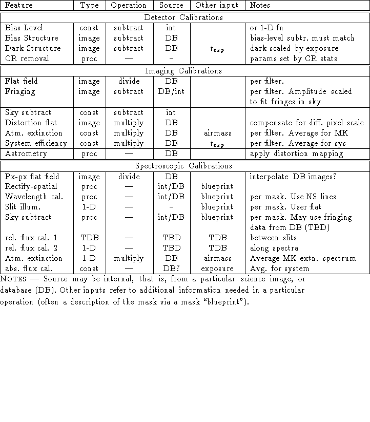 , by continuum spectra
observed through a line-of-holes mask. A series of such exposures for each
grating and at different tilts would be sufficient to map out this
vignetting. Note that there will be some interplay between the tent mirror
vignetting, grating vignetting and camera vignetting -- that is, some
shadowed regions are in common, which results in less overall vignetting
in those regions.
, by continuum spectra
observed through a line-of-holes mask. A series of such exposures for each
grating and at different tilts would be sufficient to map out this
vignetting. Note that there will be some interplay between the tent mirror
vignetting, grating vignetting and camera vignetting -- that is, some
shadowed regions are in common, which results in less overall vignetting
in those regions.
We now consider the system throughput, which is measured by comparing
spectral counts in standard star spectra with known fluxes.
We assume observations of standard stars for a particular grating tilt
but positioned at the extreme slit positions, so that the entire spectral
range for all slits is encompassed.
Ignoring the positional dependence of the blaze function leads to an error
of up to ![]() 5% under usual circumstances. Removing a theoretical blaze
function should reduce this by a factor of several.
5% under usual circumstances. Removing a theoretical blaze
function should reduce this by a factor of several.
In summary, it appears that DEIMOS slitmask spectral data can be
relative-flux-calibrated
in a pipline mode, at least to levels of ![]() 5% and probably to
5% and probably to ![]() 1-2%.
The most difficult problem is vignetting at the grating and camera mouth,
especially as the grating and tent mirror vignetting has some
overlapping shadowed regions. The most reliable way to handle this is
empirically -- that is, through a series of calibration observations, such
as a series of dome flats through a set of ``line-of-holes'' masks, observed
on a grid of grating tilts.
1-2%.
The most difficult problem is vignetting at the grating and camera mouth,
especially as the grating and tent mirror vignetting has some
overlapping shadowed regions. The most reliable way to handle this is
empirically -- that is, through a series of calibration observations, such
as a series of dome flats through a set of ``line-of-holes'' masks, observed
on a grid of grating tilts.
However, such calibration observations raise a difficulty of their own. Variations in the light source can be removed to first order by normalizing to a central slit. However, variations in the spectral shape of the illuminating source cannot be internally calibrated. We therefore require a lamp that has a constant spectral shape over the course of the calibration sequence for each grating. Certain high-pressure discharge tubes may be able to provide this stability. Without such a source, we would need to observe standard stars at each normalizing slit location and grating tilt, which is probably prohibitive in terms of observing time. [ If we adopt eight LOH masks, N grating tilts, 5 gratings, this requires 40N standard star observations.]