


Next: 7 Imaging - Procedures
Up: Part III: DEIMOS Calibration:
Previous: 5 Calibrations at Commissioning
We define three areas of a CCD image:
the prescan columns, actual CCD columns which are masked from light;
the ``active area'' that represents measurement of the charge in each
pixel of the CCD,
and the overscan columns that are produced by continuing to read the
serial register after the last ``active'' pixel in each column is measured.
While the storage location of prescan and overscan columns may vary and may
depend on one-or-two amplifier readout, their conceptual layout is shown in
Figure 6.1.
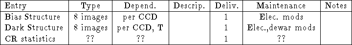
Figure 6.1: Image Layout (one-amp mode)
This chapter describes these elements:
- Bias level:
- An additive value representing the ``zero level'' in
the counts as a function of row number. Sometimes called the DC offset.
In general a one-dimensional
function determined in the overscan region (sometimes takes the form of
a constant); it is subtracted from all pixels in a given row read out
through a particular amplifier.
- Trim:
- Rewrite the image to include only the region of interest,
usually the optically active area as opposed to
(a) the prescan/overscan columns, or
(b) regions of the physical CCD that are in shadow.
Not a calibration, but usually performed while subtracting the bias level.
- Bias structure:
- Image of structure left in a bias image (ie., a zero-second dark exposure) following the bias-level subtraction.
This structure image is subtracted from other images.
Note that the bias structure image must be produced using the same bias-level
determination/subtraction as for other images.
Usually neglected if there are no strong bias-structure featues.
- Dark structure:
- Rate of dark count accumulation, per pixel. This
image must be scaled to other images by exposure time. Usually neglected, as
the dark rate is low for most pixels.
- CR-cleaning:
- Procedures for identifying and interpolating over
radiation events or ``cosmic rays.'' In practice, something of a black art,
and the exact procedure depends on imaging vs. spectral data and single vs.
multiple images of the same targets. As CRs are usually identified by their
appearance, a set of statistics characterizing typical CR images is helpful.
With the exception of CR-cleaning, the procedures described below
are all well understood and familiar to observers. The properties of
the DEIMOS science CCDs are not yet known, and may potentially require some
modifications to standard practice.
[Expected CCD properties can be found in Detector and Software CDR docs.]
[Eventually this section may include long discussion of CR-cleaning.]
- Bias level correction and trimming: In individual images,
median filter N columns of the overscan region.
Fit resultant 1-D image with a low-order polynomial function of row number.
Subtract function from each row of the image. Discard prescan and overscan
regions (trim).
- Bias structure correction:
Retrieve bias structure image from database; subtract.
- Dark structure correction:
Retrieve dark structure image from database; scale it to match the exposure
(or ``darktime''); subtract.
- CR cleaning:
(TBD)
A library of standard bias-structure and dark frames will be maintained for
each CCD.

NOTES -- Delivery: 0=Commissioning, 1=Pipeline.
Required Hardware: (none)
- 1.
- Take N bias frames (zero-exposure dark images).
- 2.
- Combine by taking the median level at each pixel (or use some
other robust level determinator that rejects cosmic rays). Note that CRs are
rare in these images.
- 3.
- Bias-level correct and trim the combined image.
- (4.)
- Depending on resultant structure, various smoothing and/or
modeling operations can be used to improve S/N. For example, an odd/even
pattern in the bias structure can be improved by replacing individual values
in each column by the average over the entire column.
The value of N should be large enough that the noise in the combined image
is insignificant compared to the read-out noise in a single image.
 -100 is generally appropriate.
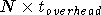
Time to acquire:
-100 is generally appropriate.
Time to acquire: 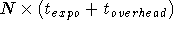 ; for N=50
and 2 min erase/read time overhead, this is about 1.7 hours for a sequence.
; for N=50
and 2 min erase/read time overhead, this is about 1.7 hours for a sequence.
- 1.
- Take N long-exposure dark frames (e.g., 1800 s each).
- 2.
- Combine by taking the median level at each pixel (or use some
other robust level determinator that rejects cosmic rays). Note that CRs are
common in these images.
- 3.
- Bias-level correct and trim the combined image.
- 4.
- Subtract the bias-structure image.
- 5.
- Scale to represent a one-second exposure.
- (6.)
- Depending on resultant structure, various smoothing and/or
modelling operations can be used to improve S/N. For example, if only
a few ``hot'' pixels or columns are present, the vast bulk of the pixels may
be set to an average dark-rate value rather than the individual values which
suffer small number fluctuations.
- (7.)
- The combined dark image may be subtracted from individual dark
images to produce a ``pure CRs'' image. CRs can be analyzed in such images
to build up statistics, e.g., what is the energy distribution? what is the
size distribution? what do typical profiles look like? These statistics
are useful for designing the CR-cleaning procedures.
The value of N should be large enough that the noise in the combined image
(following scaling to typical exposure time)
is insignificant compared to the read-out noise in a single image.
is generally a good compromise between noise and acquisition
time. Time to acquire:  ; for N=25,
0.5 hr exposures and 2 min overheads, this is 13-14 hours for a sequence.
; for N=25,
0.5 hr exposures and 2 min overheads, this is 13-14 hours for a sequence.
Instrument-control scripts and instructions to
create bias structure and dark structure frames for the database
will be required.
CR-cleaning procedures are still TDB.
There is no discussion of cosmetic defects. These are best removed at
the time of CR-cleaning, both for efficiency and because defects often
have sharp edges which can be confused with CRs.
There is no discussion of linearity.
We must determine the simplest suitable functional form for the bias level
correction during pre-commissioning tests.
We must determine the necessity of bias structure and dark structure
corrections during pre-commissioning tests.
It is probable that we can include a pixel-to-pixel response variations
(measured through a ``pixel-to-pixel flat'') as a detector calibration as
it is probably independent of color. Other response variations, such
as color-dependent variations and fringing, depend both on the detector
and its illumination and so cannot be dealt with here.
[A discussion of gain is missing in this section; gain measurements
may need to be described.]
Next: 7 Imaging - Procedures
Up: Part III: DEIMOS Calibration:
Previous: 5 Calibrations at Commissioning
DEIMOS Software Team <deimos@ucolick.org>
1997-06-13T00:18:19